Unity implements volumetric light scattering (Volumetric Light Scattering, crepuscular rays).
Principle
The principle of Volumetric Light Scattering can be referenced in "GPU Gems 3" Chapter 13The book contains effective illustrations:
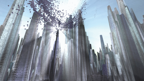
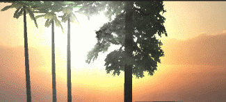
Looks good, right? Well, our goal is to achieve this effect.
The book introduces the principles, and one key formula is:
\[ L(s, \theta, \phi) = exposure \times \sum_{i=0}^n decay^i \times weight \times \frac{L( s_i, \theta_i )}{n} \]
My understanding is that for each pixel in the image, there is a possibility for light to shine upon it. Therefore, we sample the line connecting that pixel to the light source (located at the corresponding position projected onto the image) (as represented in the formula by \(i\)), and perform a weighted average of the sampled results (as indicated by the summation symbol \(\sum\)), which then serves as the new color value for that pixel. Additionally, there is a crucial post-pixel shader; however, if we solely rely on that shader to process the results rendered by the camera, it will produce noticeable artificial artifacts, resulting in many stripes.

How is the effect described in the book achieved? In fact, the book has already provided the answer, which can be explained using a series of images:
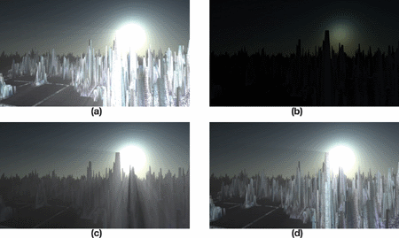
Image a shows a rough effect, where you can see many stripes if you look carefully, and there is not enough coverage to be realistic. Steps b, c, and d are required to achieve a good result.
b. Render the lighting radiation effects onto the image and include the occlusion of objects.
c. Execute the Volumetric Light Scattering pixel shader on b to achieve the occluded effect.
d. Add the colors of the real scene.
Now let's implement it step by step.
Draw covering object
In actual practice, I first use RenderWithShader to draw objects that may cause occlusion in black and the rest in white. This requires rendering each face, hence for complex scenes, it may incur some performance cost. The objects in the scene include opaque and transparent ones. We aim for opaque objects to create complete light occlusion, while transparent ones should generate partial occlusion. Therefore, we need to write different shaders for objects of different RenderTypes. RenderType is the Tag of the SubShader. If you are not sure, you can check it out hereAfter finishing writing, call:
RenderWithShader requires replacing the shader based on RenderType. In simple terms, the RenderType of the shader replacement for the same object should match the original one. This way, we can use different shaders for objects with different RenderTypes.
Shader "Custom/ObjectOcclusion"
{
    Properties
    {
        _MainTex ("Base (RGB)", 2D) = "white" {}
    }
    SubShader
    {
        Tags
        {
            "Queue" = "Geometry"
            "RenderType" = "Opaque"
        }
        LOD 200
        Pass
        {
            Lighting Off
            ZTest Always Cull Off ZWrite Off
            Fog { Mode off }
            CGPROGRAM
            #pragma vertex vert
            #pragma fragment frag
            #include "UnityCG.cginc"

            uniform sampler2D _MainTex;

            v2f_img vert(appdata_img i)
            {
                v2f_img o;
                o.pos = mul (UNITY_MATRIX_MVP, i.vertex);
                return o;
            }

            half4 frag(v2f_img i): COLOR
            {
                return half4(0, 0, 0, 1);
            }
            ENDCG
        }

    }
        SubShader
    {
        Tags
        {
            "Queue" = "Geometry"
            "RenderType" = "Transparent"
        }
        LOD 200
        Pass
        {
            Lighting Off
            ZTest Always Cull Off ZWrite Off
            Fog { Mode off }
            Blend SrcAlpha OneMinusSrcAlpha     // blend for transparent objects
            CGPROGRAM
            #pragma vertex vert
            #pragma fragment frag
            #include "UnityCG.cginc"

            uniform sampler2D _MainTex;

            v2f_img vert(appdata_img i)
            {
                v2f_img o;
                o.pos = mul (UNITY_MATRIX_MVP, i.vertex);
                o.uv = MultiplyUV( UNITY_MATRIX_TEXTURE0, i.texcoord );
                return o;
            }

            half4 frag(v2f_img i): COLOR
            {
                half3 output = (1, 1, 1);
                half4 color = tex2D(_MainTex, i.uv);
                half alpha = color.a;
                return half4(output *(1-alpha), alpha);
            }
            ENDCG
        }

    }

    FallBack "Diffuse"
}
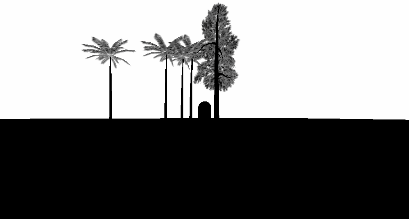
Pay attention to the difference between shaders for opaque and transparent objects: Opaque objects are straightforwardly rendered in black, while transparent objects require blending to retrieve the alpha channel from the object's texture and blend based on this alpha value. The code above only lists Opaque and Transparent shaders, in addition to TreeOpaque (similar to Opaque but with a different RenderType) and TreeTransparentCutout (similar to Transparent). By specifying the RenderType, it is essential to exhaustively cover all potential occluding objects in the scene, and here I have mentioned four types. The results are roughly as follows:
Combine object occlusion to paint light source radiation.
It's not difficult to draw the radiation of light sources. What needs attention is to make some adjustments according to the size of the screen, so that the radiation of light sources appears circular.
Shader "Custom/LightRadiate"
{
    Properties
    {
        _MainTex ("Base (RGB)", RECT) = "white" {}
        _LightPos ("Light Pos In Screen Space(XY)", Vector) = (0, 0, 0, 1)
        _LightRadius ("Light radiation radius (Pixel)", Float) = 50
    }
    SubShader
    {
        Tags { "RenderType"="Opaque" }
        LOD 200
        Pass
        {
            ZTest Always Cull Off ZWrite Off
            Fog { Mode off }
            CGPROGRAM
            #pragma vertex vert
            #pragma fragment frag
            #include "UnityCG.cginc"

            uniform sampler2D _MainTex;
            float4 _LightPos;
            float _LightRadius;

            v2f_img vert(appdata_img i)
            {
                v2f_img o;
                o.pos = mul (UNITY_MATRIX_MVP, i.vertex);
                o.uv = MultiplyUV( UNITY_MATRIX_TEXTURE0, i.texcoord );
                return o;
            }

            half4 frag(v2f_img i): COLOR
            {
                half2 deltaTexCoord = (i.uv - _LightPos.xy) * half2(_ScreenParams.x, _ScreenParams.y);
                float dis = dot(deltaTexCoord, deltaTexCoord);
                const float maxDis = _LightRadius * _LightRadius;
                dis = saturate((maxDis-dis) / maxDis * 0.5);
                return half4(dis, dis, dis, 1) * half4(tex2D(_MainTex, i.uv).rgb, 1);
            }

            ENDCG
        }
    }
    FallBack "Diffuse"
}
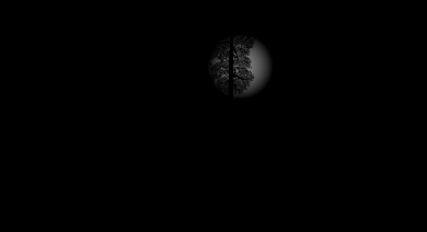
This shader requires the input of the position of the light source on the screen (which can be calculated using camera.WorldToViewportPoint, resulting in UV coordinates). Then, based on the specified radius, it draws a circle with brightness decaying outwards. This result is then combined with the previously obtained object occlusion image (stored in _MainTex). The final output looks something like this:
Handle light scattering and combine with actual colors.
Here we need to use the Pixel Shader provided in the book, my version:
Shader "Custom/LightScattering"
{
    Properties
    {
        _MainTex ("Base (RGB)", 2D) = "white" {}
        _LightRadTex("Light Radiate Tex (RGB)", 2D) = "white" {}
        _LightPos ("Light Pos In Screen Space(XY)", Vector) = (0, 0, 0, 1)
        _Params("Density Weight Decay Exposure", Vector) = (1.0, 1.0, 1.0, 1.0)
    }
    SubShader
    {
        LOD 200
        Pass
        {
            ZTest Always Cull Off ZWrite Off
            Fog { Mode off }
            CGPROGRAM
            #pragma vertex vert
            #pragma fragment frag
            #pragma target 3.0
            #include "UnityCG.cginc"

            uniform sampler2D _MainTex;
            uniform sampler2D _LightRadTex;
            uniform float4 _LightPos;
            uniform float4 _Params;

            v2f_img vert(appdata_img i)
            {
                v2f_img o;
                o.pos = mul (UNITY_MATRIX_MVP, i.vertex);
                o.uv = MultiplyUV( UNITY_MATRIX_TEXTURE0, i.texcoord );
                return o;
            }

            half4 frag(v2f_img i): COLOR
            {
                // Calculate vector from pixel to light source in screen space
                float2 deltaTexCoord = (i.uv - _LightPos.xy);

                // Divide by number of samples and scale by control factor, here I use 32 samples
                deltaTexCoord *= 1.0f / 32 * _Params.x; //density;

                // Store color.
                half3 color = tex2D(_MainTex, i.uv).rgb;

                // Store initial sample.
                half3 light = tex2D(_LightRadTex, i.uv).rgb;

                // Set up illumination decay factor.
                half illuminationDecay = 1.0f;

                for(int j = 0; j < 31; ++j)
                {
                    // Step sample location along ray.
                    i.uv -= deltaTexCoord;

                    // Retrieve sample at new location.
                    half3 sample = tex2D(_LightRadTex, i.uv).rgb;

                    // Apply sample attenuation scale/decay factors.
                    sample *= illuminationDecay * 0.03125 * _Params.y ; //weight;

                    // Accumulate combined light.
                    light += sample;

                    // Update exponential decay factor.
                    illuminationDecay *= _Params.z;             //decay;
                }

                // Output final color with a further scale control factor.
                return half4(color+(light * _Params.w), 1); // exposure
            }

            ENDCG
        }

    }
    FallBack "Diffuse"
}
Generally consistent with what is in the book, except that my parameters need to be passed into the program, and it incorporates real color maps and light scattering maps. The result:
Complete code
The code is hereAdd the "cs" script to the camera.
Original: https://wiki.disenone.site/en
This post is protected by CC BY-NC-SA 4.0 agreement, should be reproduced with attribution.
Visitors. Total Visits. Page Visits.
This post was translated using ChatGPT, please provide your feedbackPoint out any omissions.