Unity實現體積光照散射(Volumetric Light Scattering,雲隙光)
原理
(http://http.developer.nvidia.com/GPUGems3/gpugems3_ch13.html)書中關於效果的圖表:
好看吧,那好,我們的目標就是實現這種效果。
書上介紹了原理,一條關鍵的公式是:
\[ L(s, \theta, \phi) = exposure \times \sum_{i=0}^n decay^i \times weight \times \frac{L( s_i, \theta_i )}{n} \]
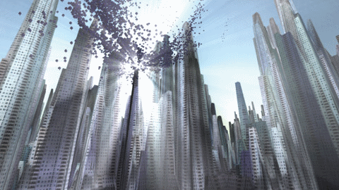
我的理解是,對於圖像上的每個像素,光線都有可能照射到,那麼對該像素到光源(在投影到圖像上的位置)的連線進行採樣(對應公式上\(i\)),採樣出的結果進行加權平均(對應公式上\(\sum\))並作為該像素的新顏色值。另外還有關鍵的後置像素著色器,但如果只是用那個著色器來對相機渲染的結果進行處理,會產生明顯的人工痕跡,有許多的條紋:

那麼書上的效果是怎麼做出來的?其實書上已經給出了答案,可以用一組圖來闡述:
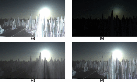
圖a就是粗糙的效果,細心地可以看到有許多條紋,並且沒有遮擋不夠真實,b、c、d就是為了獲得好的效果需要進行的步驟:
b. 將燈光輻射效果渲染到圖像上,並加上物體的遮擋
對b執行體積光散射像素著色器,以獲得遮擋後的效果。
d. 添加上真實場景的顏色
接下來讓我們一步一步地實現。
畫遮蓋物體
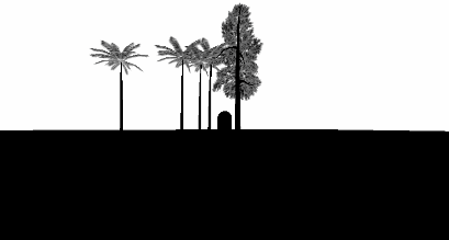
在實際的操作中,我先用RenderWithShader將會發生遮擋的物體畫成黑色,其他地方為白色,因為這需要對每個面片進行渲染,因此對於複雜的場景,會帶來一定的性能消耗。場景中的物體有不透明和透明的,我們希望不透明的物體產生完全的光線遮擋,而透明的物體應該產生部分的遮擋,那麼我們就需要針對不同RenderType的物體寫不同的Shader,RenderType是SubShader的Tag,不清楚的話可以看這裡,寫好之後調用:
RenderWithShader的第二個參數就是要求根據RenderType來替換Shader,簡單來說,同一個物體的替換的Shader的RenderType要跟替換前一致,這樣我們就可以為不同的RenderType的物體使用不同的Shader:
Shader "Custom/ObjectOcclusion"
{
    Properties
    {
        _MainTex ("Base (RGB)", 2D) = "white" {}
    }
    SubShader
    {
        Tags
        {
            "Queue" = "Geometry"
            "RenderType" = "Opaque"
        }
        LOD 200
        Pass
        {
            Lighting Off
            ZTest Always Cull Off ZWrite Off
            Fog { Mode off }
            CGPROGRAM
            #pragma vertex vert
            #pragma fragment frag
            #include "UnityCG.cginc"

            uniform sampler2D _MainTex;

            v2f_img vert(appdata_img i)
            {
                v2f_img o;
                o.pos = mul (UNITY_MATRIX_MVP, i.vertex);
                return o;
            }

            half4 frag(v2f_img i): COLOR
            {
                return half4(0, 0, 0, 1);
            }
            ENDCG
        }

    }
        SubShader
    {
        Tags
        {
            "Queue" = "Geometry"
            "RenderType" = "Transparent"
        }
        LOD 200
        Pass
        {
            Lighting Off
            ZTest Always Cull Off ZWrite Off
            Fog { Mode off }
            Blend SrcAlpha OneMinusSrcAlpha     // blend for transparent objects
            CGPROGRAM
            #pragma vertex vert
            #pragma fragment frag
            #include "UnityCG.cginc"

            uniform sampler2D _MainTex;

            v2f_img vert(appdata_img i)
            {
                v2f_img o;
                o.pos = mul (UNITY_MATRIX_MVP, i.vertex);
                o.uv = MultiplyUV( UNITY_MATRIX_TEXTURE0, i.texcoord );
                return o;
            }

            half4 frag(v2f_img i): COLOR
            {
                half3 output = (1, 1, 1);
                half4 color = tex2D(_MainTex, i.uv);
                half alpha = color.a;
                return half4(output *(1-alpha), alpha);
            }
            ENDCG
        }

    }

    FallBack "Diffuse"
}
注意不透明和透明物體的Shader之間的差別:不透明的物體直接繪製為黑色;不透明物體需要執行混合,獲取物體紋理上的alpha通道,並基於這個alpha進行混合。上面的代碼只是列舉了Opaque和Transparent,另外還有TreeOpaque(Shader跟Opaque一樣,只是改變RenderType)、TreeTransparentCutout(同Transparent)等。由於指定了RenderType,因此為了全面,需要盡可能穷盡場景中會發生遮擋的物體,我這裡就只有前面提到的四種。結果大致如下:
結合物體遮擋畫光源輻射
繪製光源的輻射並不困難,重要的是要根據屏幕的大小做一些處理,使光源的輻射形狀為圓形:
Shader "Custom/LightRadiate"
{
    Properties
    {
        _MainTex ("Base (RGB)", RECT) = "white" {}
        _LightPos ("Light Pos In Screen Space(XY)", Vector) = (0, 0, 0, 1)
        _LightRadius ("Light radiation radius (Pixel)", Float) = 50
    }
    SubShader
    {
        Tags { "RenderType"="Opaque" }
        LOD 200
        Pass
        {
            ZTest Always Cull Off ZWrite Off
            Fog { Mode off }
            CGPROGRAM
            #pragma vertex vert
            #pragma fragment frag
            #include "UnityCG.cginc"

            uniform sampler2D _MainTex;
            float4 _LightPos;
            float _LightRadius;

            v2f_img vert(appdata_img i)
            {
                v2f_img o;
                o.pos = mul (UNITY_MATRIX_MVP, i.vertex);
                o.uv = MultiplyUV( UNITY_MATRIX_TEXTURE0, i.texcoord );
                return o;
            }

            half4 frag(v2f_img i): COLOR
            {
                half2 deltaTexCoord = (i.uv - _LightPos.xy) * half2(_ScreenParams.x, _ScreenParams.y);
                float dis = dot(deltaTexCoord, deltaTexCoord);
                const float maxDis = _LightRadius * _LightRadius;
                dis = saturate((maxDis-dis) / maxDis * 0.5);
                return half4(dis, dis, dis, 1) * half4(tex2D(_MainTex, i.uv).rgb, 1);
            }

            ENDCG
        }
    }
    FallBack "Diffuse"
}
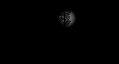
這個Shader需要輸入光源在螢幕上的位置(可以用camera.WorldToViewportPoint來計算,得到的是uv座標),然後根據指定的半徑畫一個亮度往外衰減的圓,並把結果跟前面得到的物體遮擋圖像(放在_MainTex裡)結合,結果大致為:
光散射處理,並結合真實顏色
這裡就要用到書上提供的Pixel Shader,我的版本:
Shader "Custom/LightScattering"
{
    Properties
    {
        _MainTex ("Base (RGB)", 2D) = "white" {}
        _LightRadTex("Light Radiate Tex (RGB)", 2D) = "white" {}
        _LightPos ("Light Pos In Screen Space(XY)", Vector) = (0, 0, 0, 1)
        _Params("Density Weight Decay Exposure", Vector) = (1.0, 1.0, 1.0, 1.0)
    }
    SubShader
    {
        LOD 200
        Pass
        {
            ZTest Always Cull Off ZWrite Off
            Fog { Mode off }
            CGPROGRAM
            #pragma vertex vert
            #pragma fragment frag
            #pragma target 3.0
            #include "UnityCG.cginc"

            uniform sampler2D _MainTex;
            uniform sampler2D _LightRadTex;
            uniform float4 _LightPos;
            uniform float4 _Params;

            v2f_img vert(appdata_img i)
            {
                v2f_img o;
                o.pos = mul (UNITY_MATRIX_MVP, i.vertex);
                o.uv = MultiplyUV( UNITY_MATRIX_TEXTURE0, i.texcoord );
                return o;
            }

            half4 frag(v2f_img i): COLOR
            {
                // Calculate vector from pixel to light source in screen space
                float2 deltaTexCoord = (i.uv - _LightPos.xy);

                // Divide by number of samples and scale by control factor, here I use 32 samples
                deltaTexCoord *= 1.0f / 32 * _Params.x; //density;

                // Store color.
                half3 color = tex2D(_MainTex, i.uv).rgb;

                // Store initial sample.
                half3 light = tex2D(_LightRadTex, i.uv).rgb;

                // Set up illumination decay factor.
                half illuminationDecay = 1.0f;

                for(int j = 0; j < 31; ++j)
                {
                    // Step sample location along ray.
                    i.uv -= deltaTexCoord;

                    // Retrieve sample at new location.
                    half3 sample = tex2D(_LightRadTex, i.uv).rgb;

                    // Apply sample attenuation scale/decay factors.
                    sample *= illuminationDecay * 0.03125 * _Params.y ; //weight;

                    // Accumulate combined light.
                    light += sample;

                    // Update exponential decay factor.
                    illuminationDecay *= _Params.z;             //decay;
                }

                // Output final color with a further scale control factor.
                return half4(color+(light * _Params.w), 1); // exposure
            }

            ENDCG
        }

    }
    FallBack "Diffuse"
}
大體上跟書上的一致,只是我的參數需要在程式中傳進來,並且結合了真實的顏色圖和光散射圖,結果:
完整代碼
代碼在這裡將cs腳本新增至相機。
Original: https://wiki.disenone.site/tc
This post is protected by CC BY-NC-SA 4.0 agreement, should be reproduced with attribution.
Visitors. Total Visits. Page Visits.
此貼文是透過ChatGPT翻譯的,請在反饋中指出任何遺漏之處。