Unityに触れてまだあまり経っていないですが、ShaderLabにはずっと興味があります。さまざまな表示効果を迅速に実現できると感じており、とても面白いです。まあ、まだ門を踏み入れていない私ですが、深度マップとエッジ検出に挑戦してみます。
小地图設定
私はまだプロトタイプ段階しか完成していませんので、シーンに地図を描く方法について詳細に説明するつもりはありませんが、ざっくりと言うと以下のようなことをしています。
シーンのバウンディングボックスを取得し、カメラのパラメータや位置を設定する際に役立ちます。 小さな地図カメラを正投影に設定し、バウンディングボックスに基づいてカメラの近平面と遠平面を設定します。 このテキストを日本語に翻訳します。
- カメラに人物ターゲットを追加して、ターゲットが地図の中央に表示されるようにします。
- カメラの位置を更新するたびに、ターゲットの位置やシーンの最大 y 値に基づいて行います。
具体的な配置は、後に示されるコードを参照してください。
深度マップの取得
depthTextureMode を使用して深度テクスチャを取得します。
カメラはDepthBufferまたはDepthNormalBuffer(エッジ検出に使用可能)を保存できます。設定するだけです。
その後、Shaderの中で参照します。
それで大丈夫です。具体的な方法については、後で提供するコードを参照してください。Zバッファに保存される深度値と実際の世界の深度の関係については、こちらの2つの記事を参照してください。
Learning to Love your Z-buffer,Linearize depth。また、Unityは深度を計算するためのいくつかの関数を提供しています:Linear01Depth、LinearEyeDepth など。
これが私がここで議論している重点ではありませんが、私のカメラは本来正交投影に設定されており、深度は線形であるべきなのに、テストを行ったところ線形ではありませんでした。それから、上記のリンクにある方法で実世界の深度を計算してみましたが、ずっと正しく出ませんでした。本当の線形深度を計算することもできず、UnityのZ_Bufferの問題なのか、何か他の原因なのか分かりません。もし知っている方がいれば、教えていただけるとありがたいです。当然、真の深度値が必要なわけではなく、単に深度の大きさを比較するだけなら、上記の方法で十分で、非常に簡単です。しかし、私自身の目的としては、真の深度を色値にマッピングしたいので、真の線形深度値(もちろん[0, 1]範囲のもの)が必要です。そのため、別の方法でRenderWithShaderを使用することにしました。
RenderWithShader を使用してデプスマップを取得します。
この方法は実際にはUnity Referenceにある例の一つである:Rendering with Replaced Shaders。RenderWithShaderは、シーン内の対応するメッシュを描画することを覚えておく必要があります。
シェーダーを作成する:
Shader "Custom/DepthByReplaceShader"
{
SubShader
{
    Tags { "RenderType"="Opaque" }
    Pass {
        Fog { Mode Off }
        CGPROGRAM
        #pragma vertex vert
        #pragma fragment frag
        #include "UnityCG.cginc"

        struct v2f {
            float4 pos : SV_POSITION;
            float2 depth : TEXCOORD0;
        };

        v2f vert (appdata_base v) {
            v2f o;
            o.pos = mul (UNITY_MATRIX_MVP, v.vertex);
            UNITY_TRANSFER_DEPTH(o.depth);
            return o;
        }

        float4 frag(v2f i) : COLOR {
            //UNITY_OUTPUT_DEPTH(i.depth);
            float d = i.depth.x/i.depth.y;
            return float4(d, d, d, 1);
        }
        ENDCG
    }
}
}
あなたのミニマップカメラ(なければ作成してください)にスクリプトを追加し、カメラをオーソグラフィック投影に設定します。そして、Update() の中でこのシェーダーを使用してシーンをレンダリングします:
レンダリングの結果は depthTexture に保存されます。簡単ですよね。
深度を色にマッピングする
この作業を完了するには、まず、カラー図が必要です。この図は MatLab を使用して簡単に生成できます。私が使用しているのは MatLab のジェット図です。
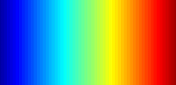
この画像をプロジェクトディレクトリ Assets\Resources に置くだけで、プログラム内で読み込むことができます:
この画像のWrap ModeはClampであるべきです。これにより、両端の色値の間で補間が行われるのを防げます。
その後、OnRenderImage と Graphics.Blit 関数を使用する必要があります。関数のプロトタイプは次のとおりです:
void OnRenderImage(RenderTexture src, RenderTexture dst);
static void Blit(Texture source, RenderTexture dest, Material mat, int pass = -1);
この関数の src はカメラのレンダリング結果で、dst は処理された結果がカメラに返されるため、通常、この関数はカメラのレンダリングが完了した後に画像効果を追加するために使用されます。たとえば、深さに対するカラーマッピングやエッジ検出といった処理に利用されます。具体的な手順は、OnRenderImage内でGraphics.Blitを呼び出し、特定のMaterialを渡すことです:
注意すべきは、Graphics.Blitが実際に行うのはこういったことです:カメラの前にスクリーンサイズと同じ平面を描画し、srcをこの平面の_MainTexとしてShaderに渡し、その結果をdstに格納します。実際のシーン内のメッシュを再描画するわけではありません。
色のマッピングというのは、深度 [0, 1] を画像の uv と見なすことです。カメラに近い部分を赤色にしたいので、深度を反転させました。
エッジ検出
エッジ検出にはカメラ自身の _CameraDepthNormalsTexture を使用する必要があります。主に法線の値を使い、深度は以前に計算したものを使用します。 _CameraDepthNormalsTexture の各ピクセル (x, y, z, w) では、(x, y) が法線で、(z, w) が深度です。法線はある方法で格納されており、興味があれば自分で調べてみてください。
コードは、Unityに組み込まれているImage Effectのエッジ検出を参考にしています。現在のピクセルの法線深度と周辺のピクセルとの差を比較し、その差が十分に大きければエッジが存在すると見なします。
inline half CheckSame (half2 centerNormal, half2 sampleNormal, float centerDepth, float sampleDepth)
{
    // difference in normals
    // do not bother decoding normals - there's no need here
    half2 diff = abs(centerNormal - sampleNormal);
    half isSameNormal = (diff.x + diff.y) < 0.5;

    // difference in depth
    float zdiff = abs(centerDepth-sampleDepth);
    // scale the required threshold by the distance
    half isSameDepth = (zdiff < 0.09 * centerDepth) || (centerDepth < 0.1);

    // return:
    // 1 - if normals and depth are similar enough
    // 0 - otherwise
    return isSameNormal * isSameDepth;
}
以下是完整的Shader:
Shader "Custom/DepthColorEdge" {

Properties
{
    _DepthTex ("Depth Tex", 2D) = "white" {}
    _ColorMap ("Color Map", 2D) = "white" {}
}
    SubShader
    {
        Tags { "RenderType"="Opaque" }
        LOD 200
        Pass
        {
            ZTest Always Cull Off ZWrite Off
            Fog { Mode off }
            CGPROGRAM
            #pragma vertex vert
            #pragma fragment frag
            #include "UnityCG.cginc"
            sampler2D _CameraDepthNormalsTexture;
            sampler2D _DepthTex;
            uniform float4 _DepthTex_TexelSize;
            sampler2D _ColorMap;
            float _ZNear;
            float _ZFar;

            struct v2f
            {
                float4 pos : SV_POSITION;
                float2 uv[3] : TEXCOORD0;
            };

            v2f vert (appdata_base v)
            {
                v2f o;
                o.pos = mul (UNITY_MATRIX_MVP, v.vertex);
                o.uv[0] = MultiplyUV( UNITY_MATRIX_TEXTURE0, v.texcoord );
                o.uv[1] = o.uv[0] + float2(-_DepthTex_TexelSize.x, -_DepthTex_TexelSize.y);
                o.uv[2] = o.uv[0] + float2(+_DepthTex_TexelSize.x, -_DepthTex_TexelSize.y);
                return o;
            }


            inline half CheckSame (half2 centerNormal, half2 sampleNormal, float centerDepth, float sampleDepth)
            {
                // difference in normals
                // do not bother decoding normals - there's no need here
                half2 diff = abs(centerNormal - sampleNormal);
                half isSameNormal = (diff.x + diff.y) < 0.5;

                // difference in depth
                float zdiff = abs(centerDepth-sampleDepth);
                // scale the required threshold by the distance
                half isSameDepth = (zdiff < 0.09 * centerDepth) || (centerDepth < 0.1);

                // return:
                // 1 - if normals and depth are similar enough
                // 0 - otherwise
                return isSameNormal * isSameDepth;
            }

            half4 frag(v2f i) : COLOR
            {
                // get color based on depth
                float depth = tex2D (_DepthTex, i.uv[0]).r;
                half4 color = tex2D(_ColorMap, float2(saturate(1-depth), 0.5));

                // detect normal diff
                half2 centerNormal = tex2D(_CameraDepthNormalsTexture, i.uv[0]).xy;
                half2 sampleNormal1 = tex2D (_CameraDepthNormalsTexture, i.uv[1]).xy;
                half2 sampleNormal2 = tex2D (_CameraDepthNormalsTexture, i.uv[2]).xy;
                float sampleDepth1 = tex2D (_DepthTex, i.uv[1]).r;
                float sampleDepth2 = tex2D (_DepthTex, i.uv[2]).r;
                color *= CheckSame(centerNormal, sampleNormal1, depth, sampleDepth1);
                color *= CheckSame(centerNormal, sampleNormal2, depth, sampleDepth2);

                return color;
            }
            ENDCG
        }

    }
    FallBack "Diffuse"
}
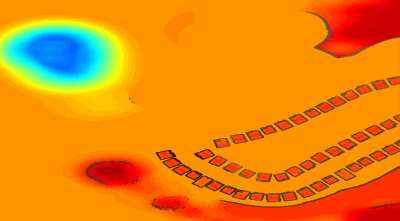
結果はこれに似ています:
混合現実世界画像
単に深度のカラーマップだけでは少し退屈かもしれませんので、実際のシーンのカラーマップを混ぜることができます。そのためには、新しいシェーダーを作成し、前の画像とカメラの実際の画像を渡し、OnRenderImage内で混合を行います。
Shader "Custom/ColorMixDepth" {
    Properties {
        _MainTex ("Base (RGBA)", 2D) = "white" {}
        _DepthTex ("Depth (RGBA)", 2D) = "white" {}
    }
    SubShader {
        Tags { "RenderType"="Opaque" }
        LOD 200

        CGPROGRAM
        #pragma surface surf Lambert

        sampler2D _MainTex;
        sampler2D _DepthTex;

        struct Input {
            float2 uv_MainTex;
            float2 uv_DepthTex;
        };

        void surf (Input IN, inout SurfaceOutput o) {
            half4 c = tex2D (_MainTex, IN.uv_MainTex);
            half4 d = tex2D (_DepthTex, IN.uv_DepthTex);
            //d = d.x == 1? 0 : d;
            o.Albedo = c.rgb*0.1 + d.rgb*0.9;
            o.Alpha = 1;
        }
        ENDCG
    }
    FallBack "Diffuse"
}
void OnRenderImage(RenderTexture src, RenderTexture dst)
{
    // if now rendering depth map
    if (isRenderDepth)
    {
        depthEdgeMaterial.SetTexture("_DepthTex", src);
        if(isUseColorMap)
            Graphics.Blit(src, dst, depthEdgeMaterial);
        else
            Graphics.Blit(src, dst);
        return;
    }
    // else rendering real color scene, mix the real color with depth map
    else
    {
        mixMaterial.SetTexture("_MainTex", src);
        mixMaterial.SetTexture("_DepthTex", depthTexture);
        Graphics.Blit(src, dst, mixMaterial);
        ReleaseTexture();
    }
}
RenderWithShaderを呼び出すときにOnRenderImageも呼び出されるということです。つまり、この関数は2回呼び出され、各呼び出しで完了する必要がある機能は異なるため、ここでは現在のレンダリング状態が深度マップを作成するか混合を行うかを示す変数を使用しています。
完整的代码
コードファイルが少し多いので、ここに置いておきましたdepth-minimap。
Original: https://wiki.disenone.site/ja
This post is protected by CC BY-NC-SA 4.0 agreement, should be reproduced with attribution.
Visitors. Total Visits. Page Visits.
この投稿はChatGPTを使用して翻訳されました。フィードバック中指出任何遗漏之处。 どんな見落としも指摘してください。